

[Huawei]interface GigabitEthernet0/0/1.1
[Huawei-GigabitEthernet0/0/1.1]ip address 192.168.1.65 27
[Huawei-GigabitEthernet0/0/1.1]Q
[Huawei]interface GigabitEthernet 0/0/1.2
[Huawei-GigabitEthernet0/0/1.2]ip address 192.168.1.97 27
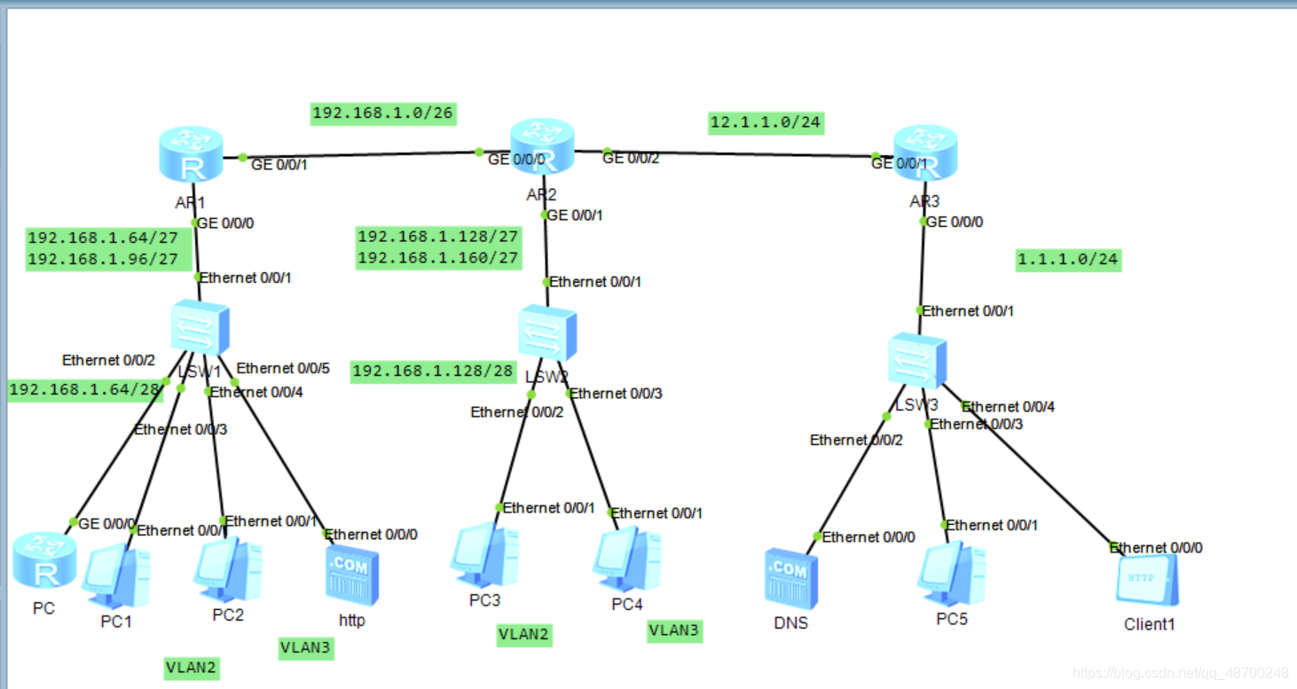
创建VLAN2、VLAN3,将HTTP服务器划分到VLAN3,将两台pc划分到VLAN2中;
[Huawei]vlan 2
[Huawei-vlan2]vlan 3
[Huawei-vlan3]q
[Huawei]interface Ethernet 0/0/2
[Huawei-Ethernet0/0/2]port link-type access
[Huawei-Ethernet0/0/2]port default vlan 2
[Huawei]interface Ethernet 0/0/3
[Huawei-Ethernet0/0/3]port link-type access
[Huawei-Ethernet0/0/3]port default vlan 2
[Huawei]interface Ethernet 0/0/4
[Huawei-Ethernet0/0/4]port link-type access
[Huawei-Ethernet0/0/4]port default vlan 3
[Huawei]dhcp enable
[Huawei]ip pool a
Info:It’s successful to create an IP address pool.
[Huawei-ip-pool-a]network 192.168.1.64 mask 27
[Huawei-ip-pool-a]gateway-list 192.168.1.65
[Huawei-ip-pool-a]dns-list 114.114.114.114 8.8.8.8

[Huawei]ip pool b
Info:It’s successful to create an IP address pool.
[Huawei-ip-pool-a]network 192.168.1.96 mask 27
[Huawei-ip-pool-a]gateway-list 192.168.1.97
[Huawei-ip-pool-a]dns-list 114.114.114.114 8.8.8.8
然后开启DHCP服务:
[Huawei]interface GigabitEthernet0/0/1.1
[Huawei-GigabitEthernet0/0/1.1]dhcp select global
[Huawei]interface GigabitEthernet0/0/1.2
[Huawei-GigabitEthernet0/0/1.2]dhcp select global
R2也与R1同理。
1、在R1上进行配置
[Huawei]ospf 1 router-id 192.168.1.1
[Huawei-ospf-1]area 0
[Huawei-ospf-1-area-0.0.0.0]network 192.168.1.0 0.0.0.255
2、在R2上进行配置
[R2]ospf 1 router-id 192.168.1.129
[R2-ospf-1]area 0
[R2-ospf-1-area-0.0.0.0]network 192.168.1.0 0.0.0.255
[LSW1]interface Ethernet 0/0/1
[LSW1-Ethernet0/0/1]port link-type trunk
[LSW1-Ethernet0/0/1]port trunk allow-pass vlan all
[LSW2]interface GigabitEthernet 0/0/1
[LSW2-GigabitEthernet0/0/1]port link-type trunk
[LSW2-GigabitEthernet0/0/1]port trunk allow-pass vlan all
配置到现在让pc1能够Ping通pc3、pc4.

[r1]aaa
[r1-aaa]local-user chen privilege level 15 password cipher 123456
[r1-aaa]local-user chen service-type telnet
[r1]user-interface vty 0 4
[r1-ui-vty0-4]authentication-mode aaa
[r2]aaa
[r2-aaa]local-user yu privilege level 15 password cipher 123456
[r2-aaa]local-user yu service-type telnet
[r2]user-interface vty 0 4
[r2-ui-vty0-4]authentication-mode aaa
然后在R1上设置策略
[r1-acl-adv-3001]rule deny tcp source 192.168.1.93 0 destination 192.168.1.1 0 destination-port eq 23
[r1-acl-adv-3001]rule deny tcp source 192.168.1.93 0 destination 192.168.1.65 0 destination-port eq 23
[r1-acl-adv-3001]rule deny tcp source 192.168.1.93 0 destination 192.168.1.97 0 destination-port eq 23
在接口上调用这个命令
[r1-GigabitEthernet0/0/1]traffic-filter inbound acl 3000
[r2-acl-basic-2000]rule permit source 192.168.0.0 0.0.255.255
[r2]interface GigabitEthernet 0/0/2
[r2-GigabitEthernet0/0/2]nat outbound 2000
然后在R2上写一条缺省路由
[r2]ip route-static 0.0.0.0 0.0.0.0 1.1.1.0
HTTP配置如下:

DNS配置如下:


在内网中的服务器进行端口映射;
[r2-GigabitEthernet0/0/2]nat static protocol tcp global current-interface 80 inside 192.168.1.98 80
Warning:The port 80 is well-known port. If you continue it may cause function failure.
Are you sure to continue?[Y/N]:y

mysql存储过程 存储过程(Stored Procedure)是一种在数据库中存储复杂程序,以便...
本文是一个ajax结合Spring MVC使用的入门,首先我们来了解一下什么是Ajax AJAX ...
那些编程高手除了写代码很厉害之外,调试代码找 bug 更是手到擒来。 编写代码只...
什么是 XHTML 标签? XHTML 标签元素是 XHTML 文档的基本组成部分。XHTML 标签可...
随着短视频的火爆,视频编辑软件也越来越吃香。一款好用的视频编辑软件能帮助用...
SQL是数据分析和处理最基本的编程语言之一,因此,无论是面试数据分析师、数据科...
本文所举的例子与保存HTML格式数据至XML类似。在以往当表格被提交后,我们通常会...
在密码学中恺撒密码英语Caesar cipher或称恺撒加密、恺撒变换、变换加密是一种最...
您的个人网站即使做得再精彩,在浩瀚如海的网络空间中,也如一叶扁舟不易为人发...
最近手痒痒,玩儿了一下Vue3.0,很舒服,赶紧把这几期Vue2.0弄完,写一些3.0的东...